 |
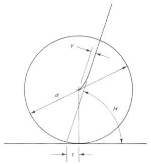
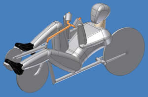
The controls design started with the front fork geometry.
By varying the trail, t, (which is a function of the wheel diameter, d,
the head tube angle, H, and the fork offset, y) the bicycle can be made
more or less controllable. We wanted a vehicle that would control easily
at higher speeds so we chose a head tube angle to compliment our already
defined fork offset and wheel diameter. The Jones relationship (y/d = 0.00917[(90°
- H)(sinH) + 4u]) was used to calculate the head tube angle. u is the stability
criteria and relates y, d, and H. More details can be found in our design
reports or in Bicycling Science 2nd Ed. |
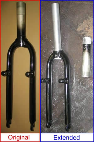
| The aluminum Dahon
fork that we got through Cycle Classics
needed a small modification before it would work with our head tube. It
needed to be extended due to the length of the head tube. We cut the old
tube loose from the fork and slid it out of its mount. A new tube was machined,
threaded, and pressed into the existing mount. |
 |
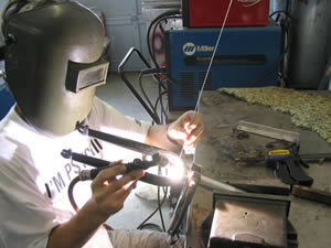 |
Aaron Bloch, one of our volunteer welders, TIG welded the
aluminum fork to the new tube. |
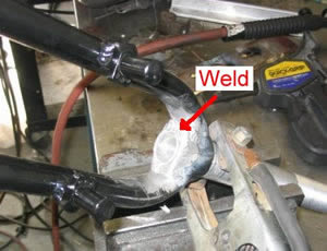
| The final weld is shown. We eventually had to grind away some
of the weld because of the oversized 20" front tire we received, but
not enough to compromise the strength. |
 |
 |
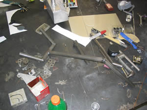
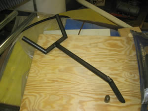
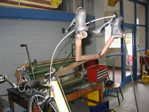
The handlebars were designed to be ergonomically comfortable
for the rider in long riding conditions and also designed to fit inside
a fairing. We also wanted to make use of the combined brake and shifter
levers from a road bike. |
| Here are the freshly welded handlebars. |
 |
 |
A custom expander bolt was made to hold the handlebars securely
in the fork tube. We machined a wedge at a 30 degree angle and welded a
insert into the joint above the 30 degree cut on the handlebar tube. A long
bolt could then be inserted through the tube a threaded into the wedge.
When tightened, the wedge expanded and gripped the inside of the fork tube.
This is a standard way of attaching bicycle handlebars. |
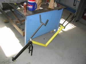
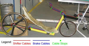
| The frame is shown with the front fork and handle bars attached. |
 |
 |
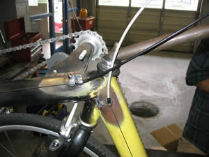
We further modified the handle bars to allow the Shimano
105 dual control levers to be attached. Tips were welded onto the handlebars
at an angle to allow the levers to function properly. |
| The cables for the brakes and shifters had to be snaked along
the frame and kept from inferring with the rider or other components. Weld-on
cable stops and cable housing were used to route the cables. The rear brake
and rear derailleur cables had to be extra long, so we purchased some tandem
cables that would work. |
 |
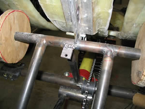 |
We were not able to mount the rear brake where the chain stays
met the frame due to clearance issues. The new rear triangle provided space
to mount the rear brake. We welded on a 1/4" thick tab and drilled
a hole to accept the brake. |
| The rear brake is mounted here. We had some clearance issues
with the brake cable hitting the back of the seat. We ended up just leaving
the brake cable with a sharp bend. It would function better if we routed
the brake cable backwards through the brake and clamped the cable to the
upper lever arm. This would take the sharp bend out. |
 |
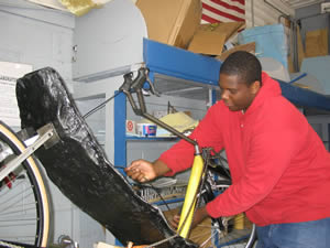 |
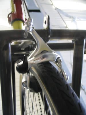
Derrell works on routing the front brake cable. The front
brake also had clearance issues with the brake cable hitting the frame.
We had to route the cable backwards through the brake and make a custom
clamp to hold the cable to the upper lever arm. |
| We used the adjustable cable stops to allow us to tension
the cables once they had stretched from use. |
 |
