 |
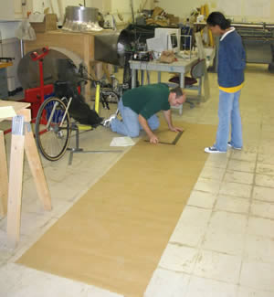
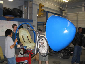
Brianne and Jimmy started the fairing design by taking the
physical boundary dimensions of the vehicle. They used large paper and several
halogen lights to project the side and top profiles of the vehicle with
the rider onto the paper. The projection was traced and a smooth aerodynamic
shape was drawn around the boundary projections. A grid was then laid out
on the paper, and the dimensions of the shape were recorded. |
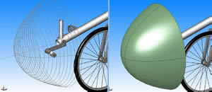
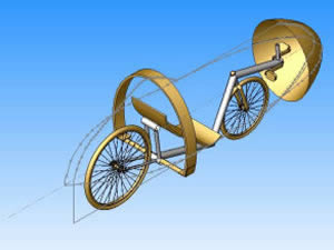
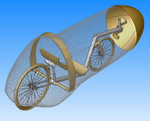
| The dimensions were transferred to Solidworks
where Nate started turning the two planar projections into a 3D model. The
nose cone was to be made from fiberglass as a separate entity. Cross sectional
traces were formed around the physical dimensions and the cone was hollowed
to the thickness of two layers of fiberglass. |
 |
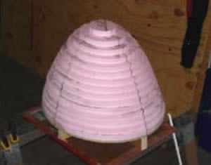 |
The cross sectional traces from the model were used to cut
layers of construction foam into the shape of the nose cone. The layers
were stacked onto each other and glued together. |
| Duct tape was used to help smooth the rigid edges of the foam
mold. |
 |
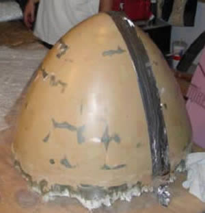 |
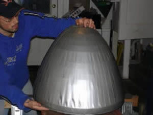
The mold was then filled with body filler and smoothed with
a wax coating. |
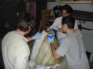
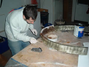
| A thick lay-up of fiberglass was needed to make a rigid female
mold. Andrew, Nate, and Bryan lay up the final layers of woven fiberglass
for the female mold. The fiberglass materials and resins were obtained from
Eastern Burlap & Trading Co.
a few blocks from the school. |
 |
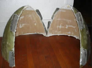 |
This is the female mold. It is rigid and has a very smooth
inner surface. The blocks are used to clamp the two part shell together
while the final nose cone is curing. The two part mold allowed for easier
removal of the nose cone. |
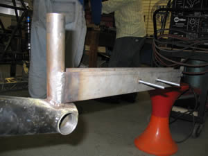
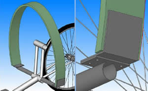
| Two pieces of flat bar were welded onto the front derailleur
tube to mount the nose cone. |
 |
 |
This shows how the nose cone was mounted. The center structural
rib in the nose cone is made of a glass reinforced foam. Wooden strips were
epoxy'ed to the foam to strengthen the bolts holes. |
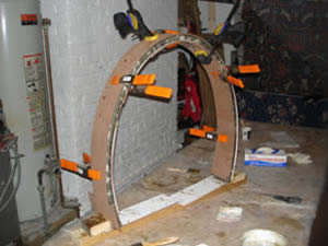
| The competition requires a roll bar capable of protecting
the rider if the vehicle flips. We opted for a composite roll bar, with
the hope of making one lighter than steel. The composite section was designed
to have a glass reinforced foam core wrapped in a layer of fiberglass. It
would attach to the frame via bolted connections to a new roll bar mount
which would be welded to the frame. |
 |
 |
This is a side view of the roll bar showing its proximity
to the seat and frame. Stress calculations were performed to prove that
the composite bar would be equally as strong as a steel counterpart. |
| The core was cut into the correct shape from sheets of glass
reinforced foam. The pieces were then sandwiched together to give the roll
bar the correct thickness. Bryan then wrapped the core with fiberglass tape
and applied the slow cure resin. |
 |
 |
After the resin was applied the roll bar was clamped to keep
the air bubbles out and to make sure the fiberglass bonded securely to the
foam core. |
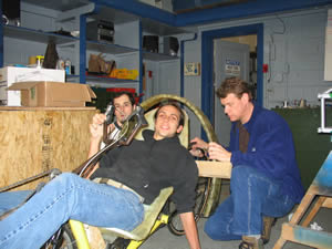
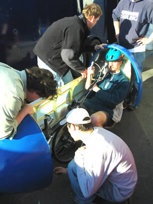
| Bryan, Jason, and Dr. Landman mock up the roll bar to make
sure there is enough headroom for the rider. After the proper position of
the roll bar was found, the steel mounting bar could be welded to the frame.
|
 |
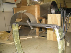 |
The ends of the mounting bar were cut to accept the plates
that were epoxy'ed onto the ends of the roll bar A slot was also milled
to accept the center tube of the rear triangle. |
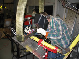
| Bryan Armstrong, another one of our volunteer welders, welds
the roll bar mounting tube to the frame of the bicycle. The frame is mounted
in the custom bike stand that Bryan also fabricated. |
 |
 |
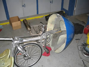
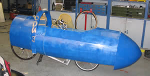
The final painted nose cone and roll bar are shown attached
to the vehicle. |
| The side and rear sections of the fairing were to be made
from bulkheads and stringers covered by a light polyester aircraft covering
material called Ceconite.
The boundary traces are shown superimposed around the bicycle frame. The
traces were further smoothed to make the final fairing shape. |
 |
 |
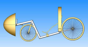
This is a wire frame shape of the first rendition for the
fairing shape. Access holes need to still be added and some of the curves
need to be toned down. |
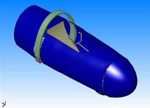
| The final fairing design consisted of the two side panels,
the nose cone, and the rear section. The side and rear sections are tied
in to the roll bar so no other mounting structure was needed. |
 |
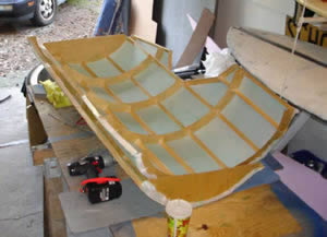 |
Light wood strips were used for the stringer and bulkhead
material. The bulkhead shapes were cut from the model dimensions and the
pieces were glued together to form the frame. The Ceconite
material was then stretched over the frame and glued into place. After the
glue was dried the Ceconite
covering was heated to shrink the material and make the skin as taught as
possible. |
| Kendrick sits in the vehicle while Andrew, Nate, Bryan, and
Dr. Landman hold the side panel up and check for clearances. Some of the
bulkheads and ribs had to be trimmed to avoid interfering with the rider.
Some extensions to the fairing side panels had to be added to bridge the
gap to the roll bar. The gap appeared when we had to move the nose cone
further forward than the originally planned. |
 |
 |
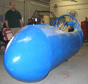
This shows a side view of the full fairing after it had been
painted blue to match the nose cone and the roll bar. |
| The dive planes and periscope will be installed after the
competition. |
 |
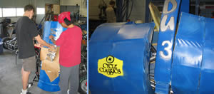 |
Brianne and Kendrick are shown removing the stencil for the
Diatom logo. A Diatom is a single-celled algae with a glass shell. The name
anticipates a fiberglass shell, even though we used Ceconite. Maybe next
time... We thought this name illustrates the organic and inorganic. The
sponsors logos and vehicle number were also stenciled on the sides. |